Numerical Parameters
A Diagrid system, primarily used in the construction of high-rise towers and skyscrapers, can fall anywhere between 20 to 100 stories tall. These heights will vary depending on building material, intended purpose of building, and location. Angles are utilized in the design process and are the main driving factor that determines member sizes and ensures structural stability.
The following parameters highlight both internal and external structural details as well as explore a typical diagrid building, 60 storey, and a maximum diagrid building, 100 storey.
External Parameters
Table 1 shows the external numerical values. That is, the span being depicted is the span of the member creating the triangular shape and the bay as seen in Figure NP1.

Figure NP1: External Values Illustration
Table 1: External Values
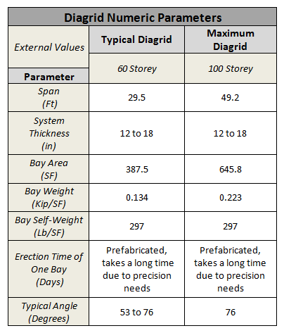
The angle of the external diagrid plays an important role in the structural design of the system. They decide how long the span of the triangular exterior members.
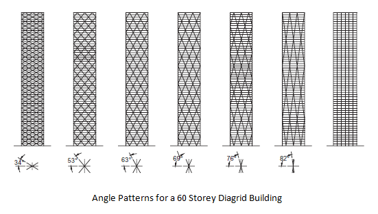
Figure NP2
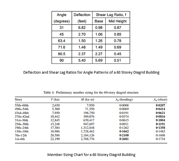
Table 2
Table 3
Internal Parameters
Optimal angle of diagonal members for maximum shear rigidity -
35 Degrees
Optimal angle of diagonal members for maximum bending rigidity - 90 Degrees
Relationship between cross-section shear force and diagonal member forces:
The member forces are related to the diagonal extensional strain, presented with next equation:
The internal span is the floor span from the exterior diagrid to the internal/core column. As seen on Figure NP3, the member span is 52' for the Gherkin floor plan. This is the assumed typical member span for this kind of structural system.
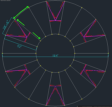
Figure NP3: The Gherkin Floor Plan
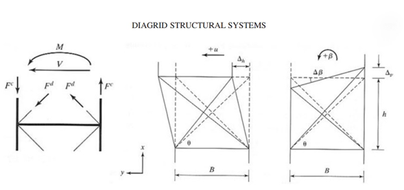
Figure NP4: Figure used for estimation of optimal angle for diagonal members
Loading Patterns

Figure NP5: Loading Applications
Figure NP5 gives us a fine representation of two different load situations (dead and wind load), and distribution of loads through the system. Both lateral and axial loads on the structure are transferred diagonally through a building from the point of application to the foundations. Because of this unique system, there is less stress applied on beams and columns. In a diagrid structure, axial forces are transferred from the inclined columns to corned columns, because of this type of load transfer there are high stress concentrations at the corners of the building and less in the middle or interior.
Furthermore, a diagrid system can have circular and square shaped buildings. Applying a diagrid in a circular shape building is more efficient for resisting buckling than in a square shaped building. Live loads (people) are one more type of loads that we have to account for in design of diagrids. Transfer of this load through the system is the same as for dead and wind load. Load is transferred diagonally through the members from the point of application to the foundations.
Comparing conventional and diagrid buildings we can see that there are big differences between shear forces and bending moments between those two systems. While we have constant values through all beams for both shear and bending moments in a conventional building, in a diagrid building values are oscillating from beam to beam. From Figure NP6 and NP7 we can conclude that most stress is applied on exterior columns and less stress is applied on interior columns in diagrid type of construction.
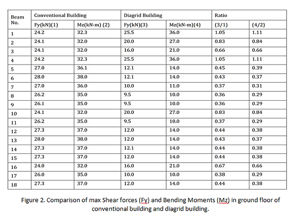
Figure NP6: Loading Comparison
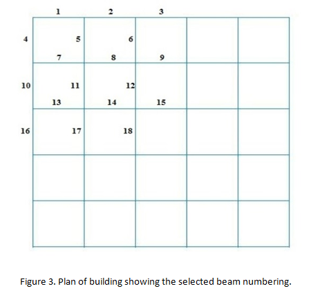
Figure NP7: Beam Numbering from Figure NP6